Oscillations and Waves: Winter-2026
HW 4a (SOLUTION): Due W4 D3
- A Triangle Wave and Your Circuit
S1 5482S
Suppose a driving voltage has the form of the triangle wave in the previous problem and is applied to the series \(LCR\) circuit you studied in the lab. We'd probably call the amplitude \(V_0\) in this case. Predict (sketch), the waveform that you would measure across the resistor if the period of the triangle driving voltage were approximately \(0.125\, ms\). Discuss your prediction, with the aim of explaining to an incoming PH424 student. I am not requesting a long calculation, but rather a succinct, mostly qualitative discussion, with (semi)quantitative bits where necessary.
If the triangle wave in the previous problem has period \(T=0.125\, ms\), its fundamental component at \(n=1\) (or angular frequency \(\omega\)) has a frequency \(f=1/T=8\,kHz\) is close to the resonant frequency of the circuit we studied.
(Note - the previous sentence is a (semi)quantitative statement ... it explain physics with numbers, but isn't a full-blown derivation).
What does that mean, the fundamental component matches the resonance of the circuit? Think about how the Fourier series works. It's a series of terms with more periods in the length of the wave as the index (of \(a_n\) or \(b_n\)) gets larger. So the \(n=1\) component will have the same wavelength as the triangle wave itself. This will be the part picked out by the resonance! The maximum currrent will look like the \(n=1\) term of the \(cos\) series.
This the largest component of the triangle wave that drives the circuit. To find the corresponding current at that frequency, we multiply by the admittance at the same frequency. At resonance, the admittance is the largest it can be! So the current at \(8\,KHz\) is large, and it is in phase with the driving frequency.
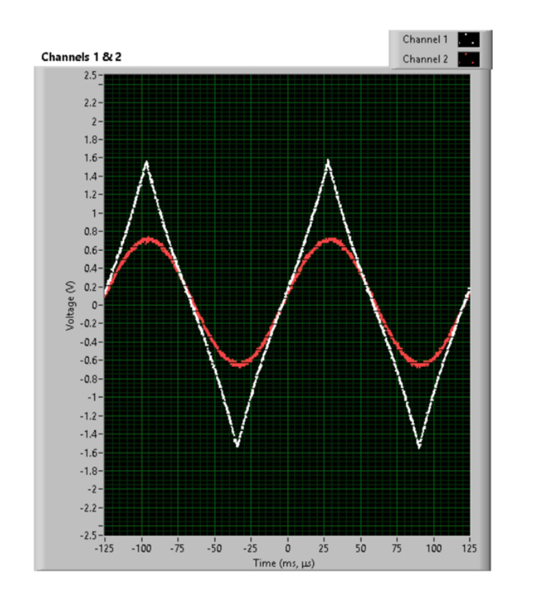
The next largest component of the driving triangle voltage is \(n=3\), at angular frequency \(3\omega\). The driving voltage at this frequency is \(9\) times smaller than the driving voltage at \(3\omega\) (resonance) AND the admittance is also much smaller at this frequency! So the contribution from anything other than the component at resonance is quite small and it depends on how good your measurement instrument is whether you see it or not. You'd mostly see a sinusoidal current at \(8\,kHz\), in phase with the triangle driver. Perhaps a small distortion due to a very small component at \(24\,kHz\).
Here is a screenshot of the actual triangle wave applied to your circuit. Thanks to Jared Smith (senior in physics) for the work