Oscillations and Waves: Spring-2025
HW 3a: Due W3 D2
- LRC Lab: Draft Experimental Setup Write \(1-2\) paragraphs that describe what measurements you made in the lab on Thursday. You should include a circuit diagram, and explain the function generator and oscilloscope.
- LRC Draft Lab Results
Show a plot (or at least a screenshot, though your report will need actual data and not a screenshot) of the oscilloscope traces to demonstrate the external voltage driving the series LRC circuit and the voltage across the resistor in the three cases \(\omega<\omega_0\), \(\omega\approx\omega_0\) and \(\omega>\omega_0\). Write sentences describing the waveforms and indicate where you measured the amplitudes and relative phases.
Make a table displaying the relevant voltages you measured and the time (and phase) differences you observed for the appropriate range of frequencies. Organize your table clearly, and make sure that columns are titled, with units given. Even if you haven't finished the measurements, you should still have a plan to organize the measurements in a well-constructed table.
- If you have any data, make a plot of the amplitude of the current in the circuit (per unit voltage applied) i.e. admittance, as a function of frequency. Also plot the relative phase as a function of frequency. Reflect on your results.
- Q factor of a Resonance Circuit
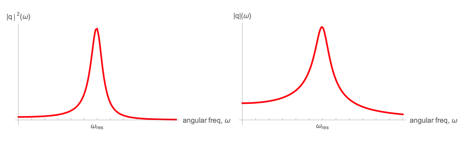
We define a “quality factor”, \(Q\equiv\frac{\omega_0}{2\beta}\), and use it as a measure of cycles in a free (undriven), damped oscillator before the oscillation decays to some smaller amplitude. The larger the number of cycles, the larger the \(Q\). Now let's see what this quantity translates to in a driven, damped oscillator. Use the example of charge amplitude\(|q|\) for a series LRC circuit.
Show that at both frequencies \(\omega=\omega_0 +\beta\) and \(\omega=\omega_0-\beta\), the magnitude of the charge response \(|q|\) is \(\frac{|q|_{max}}{\sqrt{2}}\).
(Hint -- this is a 3-line calculation. You don't need the definition of \(|q|\) in terms of \(L,\,R,\,C\)).At these frequencies, how large is the energy in the capacitor compared to the maximal energy at \(\omega\approx\omega_0\)?
- Given the above, operationally, how would you measure the \(Q\) of a resonant circuit? What is \(Q\) for your circuit?
The graphs below may help with a visual feel for the quantities discussed above:
- Steady State Solutions for the LRC Circuit
Write the equation of motion governing the charge on the capacitor in a series LRC circuit driven by an external sinusoidal voltage. Identify all parameters in your equation.
Find a steady-state solution (or particular solution) for the current in the circuit. After what time is the steady state the only relevant part of the solution, i.e., after what time has the transient solution decayed for the circuit you are working with?
- Find the steady state solution for \(\frac{dI}{dt}\) in this circuit.